QEMU仿真虚拟化
编译支持ARM64的QEMU
在x86-64的Linux Host机器上,编译QEMU,然后拉起一个ARM64的Guest Linux。编译QEMU, 为了方便调试,加入了 --enable-debug 选项,这个方便单步调试,但是会影响性能。
mkdir build
cd build
../configure --target-list=aarch64-softmmu --enable-debug
make -j
编译Linux内核可参考 编译调试ARM-Linux, 然后启动QEMU:
QEMU拉起ARM64 Linux内核
#!/bin/bash

qemu/build/aarch64-softmmu/qemu-system-aarch64 \
    -nographic \
    -cpu cortex-a57 \
    -readconfig virt.cfg
配置文件 virt.cfg,当然也可以都在命令行拉起。
[machine]
    type = "virt"
    kernel = "linux/build/arch/arm64/boot/Image"
    append = "nokaslr root=/dev/ram init=/linuxrc console=ttyAMA0 console=ttyS0"
    initrd = "initrd.ext4"

[smp-opts]
    cpus = "2"

[memory]
    size = "4G"
我们也可以在 vscode 中拉起,更加容易调试, launch.json
{
    "version": "0.2.0",
    "configurations": [
        {
            "name": "QEMU",
            "MIMode": "gdb",
            "type": "cppdbg",
            "request": "launch",
            "program": "${workspaceFolder}/build/qemu-system-aarch64",
            "cwd": "/root/arm",
            "args": [
                "-nographic",
                "-cpu", "cortex-a57",
                "-readconfig", "virt.cfg"
            ]
        }
    ]
}
这里直接使用QEMU命令行传递内核和initrd,用了QEMU内置的mini-Bootloader,关键的流程步骤:
load kernel
load initrd
load dtb
执行时的callstack如下
// 1. load kernel
#0  load_uboot_image (filename=0x555557a469b0 "linux-6.0.9/build/arch/arm64/boot/Image", ep=0x7fffffffd748, loadaddr=0x7fffffffd750, is_linux=0x7fffffffd724, image_type=2 '\002', translate_fn=0x0, translate_opaque=0x0, as=0x555557bcc6c0) at ../hw/core/loader.c:646
#1  0x00005555559a89bc in load_uimage_as (filename=0x555557a469b0 "linux-6.0.9/build/arch/arm64/boot/Image", ep=0x7fffffffd748, loadaddr=0x7fffffffd750, is_linux=0x7fffffffd724, translate_fn=0x0, translate_opaque=0x0, as=0x555557bcc6c0) at ../hw/core/loader.c:784
#2  0x0000555555df23ab in arm_setup_direct_kernel_boot (cpu=0x555557b3ca90, info=0x5555579d19b8) at ../hw/arm/boot.c:976
#3  0x0000555555df2cfe in arm_load_kernel (cpu=0x555557b3ca90, ms=0x5555579d1800, info=0x5555579d19b8) at ../hw/arm/boot.c:1239
#4  0x0000555555dfa6b2 in machvirt_init (machine=0x5555579d1800) at ../hw/arm/virt.c:2336
#5  0x00005555559b1215 in machine_run_board_init (machine=0x5555579d1800, mem_path=0x0, errp=0x7fffffffd980) at ../hw/core/machine.c:1509
#6  0x0000555555d14a46 in qemu_init_board () at ../system/vl.c:2613
#7  0x0000555555d14cb4 in qmp_x_exit_preconfig (errp=0x5555575a7f20 <error_fatal>) at ../system/vl.c:2704
#8  0x0000555555d174ed in qemu_init (argc=6, argv=0x7fffffffdc88) at ../system/vl.c:3753
#9  0x00005555561af787 in main (argc=6, argv=0x7fffffffdc88) at ../system/main.c:47

// 2. load initrd
#0  load_uboot_image (filename=0x555557a46e60 "initrd.ext4", ep=0x0, loadaddr=0x7fffffffd6f0, is_linux=0x0, image_type=3 '\003', translate_fn=0x0, translate_opaque=0x0, as=0x555557bcc6c0) at ../hw/core/loader.c:636
#1  0x00005555559a8a3c in load_ramdisk_as (filename=0x555557a46e60 "initrd.ext4", addr=1207959552, max_sz=2013265920, as=0x555557bcc6c0) at ../hw/core/loader.c:797
#2  0x0000555555df2731 in arm_setup_direct_kernel_boot (cpu=0x555557b3ca90, info=0x5555579d19b8) at ../hw/arm/boot.c:1048
#3  0x0000555555df2cfe in arm_load_kernel (cpu=0x555557b3ca90, ms=0x5555579d1800, info=0x5555579d19b8) at ../hw/arm/boot.c:1239

// 3. load dtb
#0  arm_load_dtb (addr=1241513984, binfo=0x5555579d19b8, addr_limit=0, as=0x555557bcc6c0, ms=0x5555579d1800) at ../hw/arm/boot.c:518
#1  0x0000555555df9176 in virt_machine_done (notifier=0x5555579d1958, data=0x0) at ../hw/arm/virt.c:1681
#2  0x00005555563c7f0c in notifier_list_notify (list=0x555557579390 <machine_init_done_notifiers>, data=0x0) at ../util/notify.c:39
#3  0x00005555559b1352 in qdev_machine_creation_done () at ../hw/core/machine.c:1557
#4  0x0000555555d14bbe in qemu_machine_creation_done () at ../system/vl.c:2677
#5  0x0000555555d14cbe in qmp_x_exit_preconfig (errp=0x5555575a7f20 <error_fatal>) at ../system/vl.c:2706
#6  0x0000555555d174ed in qemu_init (argc=6, argv=0x7fffffffdc88) at ../system/vl.c:3753
内核启动是需要Bootloader的,硬件初始化,把内核/DTB从文件加载到内存,PC设置到入口等等。
QEMU启动选项解析
首先说一下怎么看qemu所支持的参数
./qemu-system-aarch64 -help   // 可以看所有参数
./qemu-system-aarch64 -d help // 可以看调试所支持项
在编译的build目录下有个 qemu-options.def,也有所有的标砖的参数
展开看下QEMU启动一个machine的选项与配置
qemu_init
    // 1. qemu_add各种opts数据结构
    // 2. pass of option parsing, qemu-options.def 里有各种定义
    // QEMU_OPTION_readconfig
    |   qemu_read_config_file
    |   |   qemu_config_foreach  // 解析配置文件
    |   |       qemu_config_foreach // 跳过空行和注释解析到字典中
    |   qemu_validate_options // 从解析的字典结构判断选项合法性
    |       // 指定了 -kernel 选项,才能指定 -initrd 和 -append
    qemu_validate_options
    qemu_process_sugar_options // 有些 cpu 选项 Deprecated ,可以看文档具体
    qemu_init_main_loop
    qemu_create_machine
    |   select_machine
    |       machine_type = machine类型名字字符串
    |       machine_class = find_machine(machine_type, machines);
    |       current_machine = MACHINE(object_new_with_class(OBJECT_CLASS(machine_class))); // 全局变量machine
    machine_class = MACHINE_GET_CLASS(current_machine);
    current_machine->cpu_type = xx // 解析CPU类型
    qmp_x_exit_preconfig
        qemu_init_board
        |   machine_run_board_init
        |       machine_class = MACHINE_GET_CLASS(machine);
        |       machine_class->init(machine); // 函数指针是 machvirt_init
        |           cpuobj = object_new(possible_cpus->cpus[n].type); // 初始化cpu对象
        |           object_property_set_bool(cpuobj, "has_el3", false, NULL); // 如果secure模式
        |           create_gic
        |           create_uart
        |           ... // 各种设备create
        |           vms->bootinfo = .. // 赋值 bootinfo
        |               arm_load_kernel
        |                   arm_setup_direct_kernel_boot
        qemu_machine_creation_done
            arm_load_dtb
上面就是使用QEMU解析命令行参数和配置文件启动virt(arm machine)跑Linux的流程。
ARM架构的仿真支持
https://www.qemu.org/docs/master/system/target-arm.html
ARM由于是开放授权的,有很多种硬件。上面链接就说明了当前QEMU所支持的仿真硬件。如果不是跟真实硬件所对应,只是为了跑linux,建议使用 vrit machine. virt supports PCI, virtio, recent CPUs and large amounts of RAM.
有时候,看源码 rst 反而更方便,这种在vim里快速浏览查找所支持的device,IP,总线等。每个ARM machine可以快速看 Supported devices 列表。比如:
在 qemu/docs/system/arm 目录:
I2C/SPI/PCI/PICe/GPIO/USB
RTC/UART/NOR Flash/91C111 Ethernet Controller
GIC/DDR/Timer/Watchdog timer/
E1000E ethernet card on PCIe bus
一个查所有device的命令: qemu -device help
串口的仿真
QEMU的virt machine支持多种串口设备,最常用的是 pl011, 也就是ARM PrimeCell PL011 UART。这个是ARM的一个标准外设。
Data Register, UARTDR 的偏移是0,屏幕打印就是这个寄存器的值。点开细节描述就是: 7:0 就是 data. 看QEMU pl011.c实现:
pl011_write()
    case 0: ch = value; // 这个就是要打印的value
    qemu_chr_fe_write_all(&s->chr, &ch, 1); // 这个换成printf仍然可以打出来值
        qemu_chr_write // char设备的backend实现
一个执行的流程
(gdb) b writev
(gdb) bt
#0  __GI___writev (fd=1, iov=0x7ffe5b9fa450, iovcnt=1) at ../sysdeps/unix/sysv/linux/writev.c:25
<||>
#1  0x00005555561ca6c9 in qio_channel_file_writev (ioc=0x555557a26390, iov=0x7ffe5b9fa450, niov=1, fds=0x0, nfds=0, flags=0, errp=0x0) at ../io/channel-file.c:126
#2  0x00005555561d353e in qio_channel_writev_full (ioc=0x555557a26390, iov=0x7ffe5b9fa450, niov=1, fds=0x0, nfds=0, flags=0, errp=0x0) at ../io/channel.c:109
#3  0x00005555562e8090 in io_channel_send_full (ioc=0x555557a26390, buf=0x7ffe5b9fa75c, len=1, fds=0x0, nfds=0) at ../chardev/char-io.c:123
#4  0x00005555562e813e in io_channel_send (ioc=0x555557a26390, buf=0x7ffe5b9fa75c, len=1) at ../chardev/char-io.c:146
#5  0x00005555562f2a7a in fd_chr_write (chr=0x5555576e7740, buf=0x7ffe5b9fa75c "[\177", len=1) at ../chardev/char-fd.c:45
#6  0x00005555562efe2f in qemu_chr_write_buffer (s=0x5555576e7740, buf=0x7ffe5b9fa75c "[\177", len=1, offset=0x7ffe5b9fa560, write_all=false) at ../chardev/char.c:122
#7  0x00005555562effdb in qemu_chr_write (s=0x5555576e7740, buf=0x7ffe5b9fa75c "[\177", len=1, write_all=false) at ../chardev/char.c:174
#8  0x00005555562e6ea0 in qemu_chr_fe_write (be=0x55555794ccc0, buf=0x7ffe5b9fa75c "[\177", len=1) at ../chardev/char-fe.c:42
#9  0x00005555562e82cb in mux_chr_write (chr=0x55555794cc00, buf=0x7ffe5b9fa75c "[\177", len=1) at ../chardev/char-mux.c:49
#10 0x00005555562efe2f in qemu_chr_write_buffer (s=0x55555794cc00, buf=0x7ffe5b9fa75c "[\177", len=1, offset=0x7ffe5b9fa6d0, write_all=true) at ../chardev/char.c:122
#11 0x00005555562effdb in qemu_chr_write (s=0x55555794cc00, buf=0x7ffe5b9fa75c "[\177", len=1, write_all=true) at ../chardev/char.c:174
#12 0x00005555562e6eea in qemu_chr_fe_write_all (be=0x555557d01cb0, buf=0x7ffe5b9fa75c "[\177", len=1) at ../chardev/char-fe.c:53
<||>
#13 0x000055555599535b in pl011_write (opaque=0x555557d017f0, offset=0, value=91, size=4) at ../hw/char/pl011.c:268
#14 0x00005555561413a2 in memory_region_write_accessor (mr=0x555557d01b20, addr=0, value=0x7ffe5b9fa878, size=4, shift=0, mask=4294967295, attrs=...) at ../system/memory.c:497
#15 0x00005555561416b9 in access_with_adjusted_size (addr=0, value=0x7ffe5b9fa878, size=2, access_size_min=4, access_size_max=4, access_fn=0x5555561412a8 <memory_region_write_accessor>, mr=0x555557d01b20, attrs=...) at ../system/memory.c:573
#16 0x00005555561447e7 in memory_region_dispatch_write (mr=0x555557d01b20, addr=0, data=91, op=MO_16, attrs=...) at ../system/memory.c:1521
#17 0x000055555619c498 in int_st_mmio_leN (cpu=0x555557b3e370, full=0x7ffe54141f50, val_le=91, addr=18446603336393150464, size=2, mmu_idx=2, ra=140734882528523, mr=0x555557d01b20, mr_offset=0) at ../accel/tcg/cputlb.c:2545
#18 0x000055555619c5f6 in do_st_mmio_leN (cpu=0x555557b3e370, full=0x7ffe54141f50, val_le=91, addr=18446603336393150464, size=2, mmu_idx=2, ra=140734882528523) at ../accel/tcg/cputlb.c:2581
#19 0x000055555619cd2d in do_st_2 (cpu=0x555557b3e370, p=0x7ffe5b9faa10, val=91, mmu_idx=2, memop=MO_16, ra=140734882528523) at ../accel/tcg/cputlb.c:2739
#20 0x000055555619d06f in do_st2_mmu (cpu=0x555557b3e370, addr=18446603336393150464, val=91, oi=18, ra=140734882528523) at ../accel/tcg/cputlb.c:2812
#21 0x000055555619db37 in helper_stw_mmu (env=0x555557b40b30, addr=18446603336393150464, val=91, oi=18, retaddr=140734882528523) at ../accel/tcg/ldst_common.c.inc:93
#22 0x00007fff64ae3d56 in code_gen_buffer ()
<...tcg thread...>
上面断了 POSIX 标准库中的 writev 函数,主要用途在于提高写入操作的效率,特别是当需要将多个不连续的数据缓冲区写入时。
然后就是捕获键盘的输入,这个肯定涉及了interrupt,等OS启动到串口可以命令是,给 pl011 中报中断的地方打断点
// gic interrupt
#0  cpu_interrupt (cpu=0x555557b3e370, mask=2) at ../system/cpus.c:255
#1  0x0000555555e83bfc in arm_cpu_set_irq (opaque=0x555557b3e370, irq=0, level=1) at ../target/arm/cpu.c:954
#2  0x00005555561b8040 in qemu_set_irq (irq=0x555557b26420, level=1) at ../hw/core/irq.c:44
#3  0x0000555555a73d0a in gic_update_internal (s=0x555557c869f0, virt=false) at ../hw/intc/arm_gic.c:222
#4  0x0000555555a73d7f in gic_update (s=0x555557c869f0) at ../hw/intc/arm_gic.c:229
#5  0x0000555555a74639 in gic_set_irq (opaque=0x555557c869f0, irq=33, level=1) at ../hw/intc/arm_gic.c:419
#6  0x00005555561b8040 in qemu_set_irq (irq=0x555557bee5c0, level=1) at ../hw/core/irq.c:44
<||> // pl011
#7  0x0000555555994de4 in pl011_update (s=0x555557d017f0) at ../hw/char/pl011.c:120
#8  0x00005555559956f7 in pl011_put_fifo (opaque=0x555557d017f0, value=97) at ../hw/char/pl011.c:358
#9  0x0000555555995729 in pl011_receive (opaque=0x555557d017f0, buf=0x7fffffffc9c0 "a\317\377\377\377\177", size=1) at ../hw/char/pl011.c:364
<||> // char backend, 这里键盘输入的是a, buf里value就是a
#10 0x00005555562e8c4b in mux_chr_read (opaque=0x55555794cc00, buf=0x7fffffffc9c0 "a\317\377\377\377\177", size=1) at ../chardev/char-mux.c:235
#11 0x00005555562f00d7 in qemu_chr_be_write_impl (s=0x5555576e7740, buf=0x7fffffffc9c0 "a\317\377\377\377\177", len=1) at ../chardev/char.c:202
#12 0x00005555562f013f in qemu_chr_be_write (s=0x5555576e7740, buf=0x7fffffffc9c0 "a\317\377\377\377\177", len=1) at ../chardev/char.c:214
#13 0x00005555562f2bb3 in fd_chr_read (chan=0x5555576ed090, cond=G_IO_IN, opaque=0x5555576e7740) at ../chardev/char-fd.c:72
#14 0x00005555561cf5b1 in qio_channel_fd_source_dispatch (source=0x5555586664a0, callback=0x5555562f2a7c <fd_chr_read>, user_data=0x5555576e7740) at ../io/channel-watch.c:84
<||> // event loop
#15 0x00007ffff736b04e in g_main_context_dispatch () at /lib/x86_64-linux-gnu/libglib-2.0.so.0
#16 0x00005555563dae7d in glib_pollfds_poll () at ../util/main-loop.c:290
#17 0x00005555563daefb in os_host_main_loop_wait (timeout=510442109) at ../util/main-loop.c:313
#18 0x00005555563db00c in main_loop_wait (nonblocking=0) at ../util/main-loop.c:592
#19 0x0000555555d0f0b5 in qemu_main_loop () at ../system/runstate.c:782
#20 0x00005555561b04e4 in qemu_default_main () at ../system/main.c:37
#21 0x00005555561b0523 in main (argc=6, argv=0x7fffffffdc88) at ../system/main.c:48
在上面的第5层栈帧,可以看到 irq=33, 而前面前面一层调用还是irq=1, 跟virt的DTS一致,参考: QEMU导出dts
pl011@9000000 {
    clock-names = "uartclk\0apb_pclk";
    clocks = <0x8000 0x8000>;
    interrupts = <0x00 0x01 0x04>;
    reg = <0x00 0x9000000 0x00 0x1000>;
    compatible = "arm,pl011\0arm,primecell";
};
这里面QEMU做了一个特殊的处理,看第5层函数栈帧实现:
/* Process a change in an external IRQ input.  */
static void gic_set_irq(void *opaque, int irq, int level)
{
    /* Meaning of the 'irq' parameter:
    *  [0..N-1] : external interrupts
    *  [N..N+31] : PPI (internal) interrupts for CPU 0
    *  [N+32..N+63] : PPI (internal interrupts for CPU 1
    *  ...
    */
    if (irq < (s->num_irq - GIC_INTERNAL))
        /* The first external input line is internal interrupt 32.  */
        irq += GIC_INTERNAL; // GIC_INTERNAL 32
}
这里就对中断号做了特殊处理,external interrupts 是所有核共享的,放到到 [0, N-1], 而前32个中断号是每个核私有的,可以看那 ARM体系结构 里GIC章节。每个核私有中断包括了SGI/PPI,这样好处就是让CPU核和中断编号就对应了起来了,就又了注释中所说明的, [N..N+31] 就是CPU0, 然后就是CPU1。巧妙在数据结构关系中建立了这个逻辑。
后面可以看下 Linux 内核里相关的实现再。
中断的仿真
查看Guest的中断统计
前面的mini-virt启动,只用到arch timer和uart中断,其他的其实没有用到,至少在启动这个最小的内核Guest的时候。而且,代码精简后,也更加方便清楚每一行的功能是干嘛的,方便系统性的了解。启动OS后,可以通过下面的命令来看哪些中断增长了。
# cat proc/interrupts
           CPU0       CPU1
  10:       791       2186     GICv3  30 Level     arch_timer
  11:         0          0     GICv3  27 Level     kvm guest vtimer
  13:        34          0     GICv3  33 Level     uart-pl011
IPI0:        16         25       Rescheduling interrupts
IPI1:       457        266       Function call interrupts
IPI2:         0          0       CPU stop interrupts
IPI3:         0          0       CPU stop (for crash dump) interrupts
IPI4:         0          0       Timer broadcast interrupts
IPI5:         0          0       IRQ work interrupts

连续敲击两次,可以看那些中断在增长,CPU0这个第二列就是中断个数统计。
关于中断号:
arch_timer  30    //  #define ARCH_TIMER_NS_EL1_IRQ  30   @hw/arm/bsa.h
uart-pl011  33    //  SPI interrupt:   [VIRT_UART] =  1   @hw/arm/mini-virt.c
中断上报给CPU的实现
QEMU在tcg大循环不停的翻译执行Guest的指令,然后遇到了IO/Exception后,就去执行对应处理,比如下面中断的一个callstack
(gdb) bt
#0  cpu_exit (cpu=0x5555563bf3fb <qemu_cond_broadcast+71>) at ../hw/core/cpu-common.c:85
#1  0x00005555561aa4fe in mttcg_kick_vcpu_thread (cpu=0x555557b3d370) at ../accel/tcg/tcg-accel-ops-mttcg.c:130
#2  0x0000555555d00121 in qemu_cpu_kick (cpu=0x555557b3d370) at ../system/cpus.c:462
#3  0x00005555561a9d9c in tcg_handle_interrupt (cpu=0x555557b3d370, mask=2) at ../accel/tcg/tcg-accel-ops.c:100
<||>
#4  0x0000555555cffb21 in cpu_interrupt (cpu=0x555557b3d370, mask=2) at ../system/cpus.c:256
#5  0x0000555555e82e75 in arm_cpu_set_irq (opaque=0x555557b3d370, irq=0, level=1) at ../target/arm/cpu.c:954
#6  0x00005555561b72ad in qemu_set_irq (irq=0x555557b25420, level=1) at ../hw/core/irq.c:44
中断报上来后,在tcg里面设置一个标记,大循环中检测到后,pc指针设置到中断向量表的位置去执行中断。在 mini-virt 这个machine中的create_gic函数里,通过QOM property机制指定gic版本,cpu核数,中断个数。
GICR的关键属性设置
根据 GIC中断控制器 ARM官方GIC说明,每个核一个GICR,而且每个GICR也需要足够的MMIO空间,最终的GICR个数根据特定逻辑算出来后通过property设置给gic的redist-region-count属性。
备注
Our GICv3 QOM interface includes an array property redist-region-count which allows board models to specify that the registributor registers are not in a single contiguous range, but split into multiple pieces. We implemented this for KVM, but currently the TCG GICv3 model insists that there is only one region.
关于GICR的一些属性设置
/*
* The redistributor in GICv3 has two 64KB frames per CPU; in
* GICv4 it has four 64KB frames per CPU.
*/
#define GICV3_REDIST_SIZE 0x20000  // == 2*64KB
#define GICV4_REDIST_SIZE 0x40000  // == 4*64KB

这个通过property数组机制设置redist-region-count的比较精妙。首先是一个链表,然后链表在设置给array的时候,会重新申请一个
array的数组,因为后面已经知道了大小了,赋值给array后,再把这个临时的链表给释放掉,watch了这个属性的值,callstack如下:

#0  set_prop_array (obj=0x555557d298d0, v=0x555557d2e750, name=0x55555663b431 "redist-region-count", opaque=0x5555573c9210 <arm_gicv3_common_properties+528>, errp=0x5555575aaf58 <error_abort>) at ../hw/core/qdev-properties.c:675
#1  0x00005555561b21f1 in field_prop_set (obj=0x555557d298d0, v=0x555557d2e750, name=0x55555663b431 "redist-region-count", opaque=0x5555573c9210 <arm_gicv3_common_properties+528>, errp=0x5555575aaf58 <error_abort>) at ../hw/core/qdev-properties.c:88
#2  0x00005555561bdfe4 in object_property_set (obj=0x555557d298d0, name=0x55555663b431 "redist-region-count", v=0x555557d2e750, errp=0x5555575aaf58 <error_abort>) at ../qom/object.c:1435
#3  0x00005555561c258e in object_property_set_qobject (obj=0x555557d298d0, name=0x55555663b431 "redist-region-count", value=0x555557d176a0, errp=0x5555575aaf58 <error_abort>) at ../qom/qom-qobject.c:28
#4  0x00005555561b3f01 in qdev_prop_set_array (dev=0x555557d298d0, name=0x55555663b431 "redist-region-count", values=0x555557d176a0) at ../hw/core/qdev-properties.c:854
#5  0x0000555555dfeca5 in create_gic (vms=0x555557919000, mem=0x555557748ee0) at ../hw/arm/mini-virt.c:62
#6  0x0000555555dff2ee in mach_virt_init (machine=0x555557919000) at ../hw/arm/mini-virt.c:148

可以看 set_prop_array 的实现,有这个拷贝的总做,这个最终的目的都是为了支持多GICR的region.

@type: struct GICv3State
    MemoryRegion iomem_dist; /* Distributor */
    GICv3RedistRegion *redist_regions; /* Redistributor Regions */
    uint32_t *redist_region_count; /* redistributor count within each region */
    uint32_t nb_redist_regions; /* number of redist regions */
@type: struct GICv3RedistRegion
    // The redistributor pages might be split into more than one region
    // on some machine types if there are many CPUs.
GIC和CPU的中断pin连接
在machine的初始化创建函数中,create完毕cpu和gic后,就需要把相关的中断pin给连接起来,保证中断的正常上报了,代码流程:
#define NUM_IRQS 256  // Number of external interrupt lines to configure the GIC with
SysBusDevice *gicbusdev = SYS_BUS_DEVICE(vms->gic);
// 中断的总数,针对1个core,32是每个core私有独占,其他的是所有core共享
qdev_prop_set_uint32(vms->gic, "num-irq", NUM_IRQS + 32); // 0~31 is SGI/PPI
for (int i = 0; i < smp_cpus; i++) {
    DeviceState *cpudev = DEVICE(qemu_get_cpu(i));
    int intidbase = NUM_IRQS + i * GIC_INTERNAL; // GIC_INTERNAL == 32
    // ARCH_TIMER_NS_EL1_IRQ 30 (Non-Secure EL1 arch-timer)
    // 连接到一个device的output GPIO line,当assert这个line,对应的qemu_irq callback会被调用
    //      第二个参数:Number of the anonymous output GPIO line,必须在范围内
    //      第三个参数:pin: qemu_irq to connect the output line to(一个结构体,内部有回调函数)
    qdev_connect_gpio_out(cpudev, 0, qdev_get_gpio_in(vms->gic, intidbase + ARCH_TIMER_NS_EL1_IRQ));
        qdev_connect_gpio_out_named(dev, NULL, n, input_pin);
            object_property_set_link(OBJECT(dev), propname, OBJECT(input_pin), &error_abort);
            // @propname: "unnamed-gpio-out[0]"
            // @input_pin->handler: <gicv3_set_irq>
    <||>
    // #define ARM_CPU_IRQ 0, ARMCPU object's four inbound GPIO lines
    //      有4个:ARM_CPU_FIQ 1, ARM_CPU_VIRQ 2, ARM_CPU_VFIQ 3
    // sysbus_connect_irq:
    sysbus_connect_irq(gicbusdev, i, qdev_get_gpio_in(cpudev, ARM_CPU_IRQ));
        // 这里gic转成了父类 sysbusdev, 这里比较隐秘的用父类初始化了 gpio out, 看后面callstack
        SysBusDeviceClass *sbd = SYS_BUS_DEVICE_GET_CLASS(dev);
        //  Connect one of a device's named output GPIO lines
        //  arg2: Name of the output GPIO array;  这里 #define SYSBUS_DEVICE_GPIO_IRQ "sysbus-irq"
        //  arg3: Number of the anonymous output GPIO line
        //  arg4: qemu_irq to connect the output line to
        qdev_connect_gpio_out_named(DEVICE(dev), SYSBUS_DEVICE_GPIO_IRQ, n, irq); // dev <-- gicbusdev
                object_property_set_link(OBJECT(dev), propname, OBJECT(input_pin), &error_abort);
                    // @propname: "sysbus-irq[0]"
                    // @input->hander: <arm_cpu_set_irq>
}
大概的中断连接拓扑如下图:
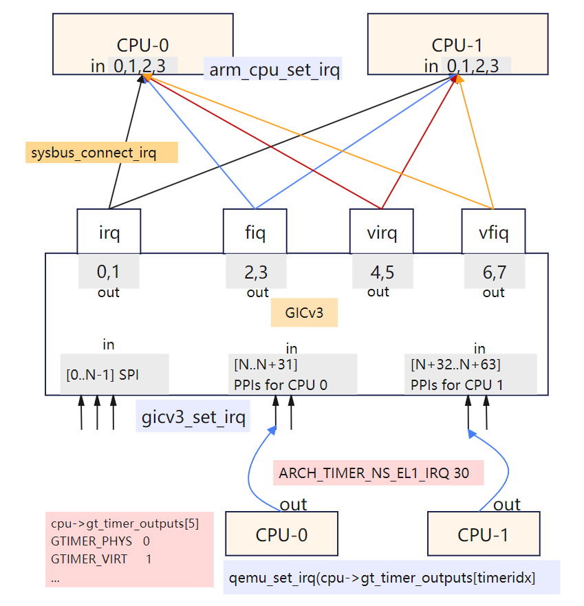
ARM手册里规定 0~31 是SGI/PPI, 后面在连线gic和cpu时,看看各自设备对中断的实现。
对于CPU的连接线
// @cpu.c
arm_cpu_initfn
    // create an array of anonymous input GPIO lines
    //    arg2:Function to call when GPIO line value is set
    //    arg3: Number of GPIO lines to create
    qdev_init_gpio_in(DEVICE(cpu), arm_cpu_set_irq, 4);
    |
    arm_cpu_set_irq
    |   [ARM_CPU_IRQ] = CPU_INTERRUPT_HARD // mask[] , #define CPU_INTERRUPT_HARD  0x0002
    |   cpu_interrupt(cs, mask[irq]);
    |       // then tcg loop will proc interrupt
    |
    // generic timer
    // create an array of anonymous output GPIO lines
    //  The device implementation can then raise and lower the GPIO line by calling qemu_set_irq()
    //      If anything is connected to the other end of the GPIO this will cause the handler function
    //      for that input GPIO to be called.
    // GTIMER_PHYS 0; GTIMER_VIRT 1; GTIMER_HYP 2; GTIMER_SEC 3; GTIMER_HYPVIRT 4;
    qdev_init_gpio_out(DEVICE(cpu), cpu->gt_timer_outputs, ARRAY_SIZE(cpu->gt_timer_outputs));
        qdev_init_gpio_out_named(dev, pins, NULL, n);
            memset(pins, 0, sizeof(*pins) * n); // gpio_out pins在外部内存申请好了,这里设置0
            // 关联一个命名属性,从而方便后续 connect irq时,通过属性的名字,赋值 qemu_irq 的值
            object_property_add_link(OBJECT(dev), propname, TYPE_IRQ, (Object **)&pins[i]
            gpio_list->num_out += n; // 这里有个总计数,方便connect的时候连接上去
对于 gic 初始化连接线
// // gic 初始化gpio_in
#0  qdev_init_gpio_in_named (dev=0x555557d28670, handler=0x555555a7caee <gicv3_set_irq>, name=0x0, n=320) at /root/github/qemu/include/hw/qdev-core.h:836
#1  0x00005555559a4158 in qdev_init_gpio_in (dev=0x555557d28670, handler=0x555555a7caee <gicv3_set_irq>, n=320) at ../hw/core/gpio.c:71
#2  0x0000555555a7ab29 in gicv3_init_irqs_and_mmio (s=0x555557d28670, handler=0x555555a7caee <gicv3_set_irq>, ops=0x55555738dea0 <gic_ops>) at ../hw/intc/arm_gicv3_common.c:288
#3  0x0000555555a7cd01 in arm_gic_realize (dev=0x555557d28670, errp=0x7fffffffd5d0) at ../hw/intc/arm_gicv3.c:401
|| property proc
#11 0x00005555559b8965 in sysbus_realize_and_unref (dev=0x555557d28670, errp=0x5555575a9f60 <error_fatal>) at ../hw/core/sysbus.c:261
#12 0x0000555555dfec83 in create_gic (vms=0x555557918000, mem=0x555557747ee0) at ../hw/arm/mini-virt.c:65
#13 0x0000555555dff2a2 in mach_virt_init (machine=0x555557918000) at ../hw/arm/mini-virt.c:148

// gic 初始化gpio_out
#0  qdev_init_gpio_out_named (dev=0x555557d28650, pins=0x555557d2d6c0, name=0x5555564e8301 "sysbus-irq", n=1) at ../hw/core/gpio.c:94
#1  0x00005555559b854f in sysbus_init_irq (dev=0x555557d28650, p=0x555557d2d6c0) at ../hw/core/sysbus.c:181
#2  0x0000555555a7ab5f in gicv3_init_irqs_and_mmio (s=0x555557d28650, handler=0x555555a7caee <gicv3_set_irq>, ops=0x55555738dea0 <gic_ops>) at ../hw/intc/arm_gicv3_common.c:291
#3  0x0000555555a7cd01 in arm_gic_realize (dev=0x555557d28650, errp=0x7fffffffd5d0) at ../hw/intc/arm_gicv3.c:401
|| // property process
#10 0x00005555561b571a in qdev_realize_and_unref (dev=0x555557d28650, bus=0x555557a371c0, errp=0x5555575a9f60 <error_fatal>) at ../hw/core/qdev.c:299
#11 0x00005555559b8965 in sysbus_realize_and_unref (dev=0x555557d28650, errp=0x5555575a9f60 <error_fatal>) at ../hw/core/sysbus.c:261
#12 0x0000555555dfec83 in create_gic (vms=0x555557918000, mem=0x555557747ee0) at ../hw/arm/mini-virt.c:65
#13 0x0000555555dff2a2 in mach_virt_init (machine=0x555557918000) at ../hw/arm/mini-virt.c:148

arm_gic_realize //  @file: arm_gicv3.c
    gicv3_init_irqs_and_mmio (s=0x555557d28670, handler= <gicv3_set_irq>, ops= <gic_ops>) // arm_gicv3_common.c
        // For the GIC, also expose incoming GPIO lines for PPIs for each CPU.
        // GPIO array layout is thus: [0..N-1] spi; [N..N+31] PPIs for CPU 0; [N+32..N+63] PPIs for CPU 1; ...
        i = s->num_irq - GIC_INTERNAL + GIC_INTERNAL * s->num_cpu; // 总数
        qdev_init_gpio_in(DEVICE(s), handler, i);
        |   // create an array of input GPIO lines
        |   qdev_init_gpio_in_named(dev, handler, NULL, n)
        |       qdev_init_gpio_in_named_with_opaque
        |           // type就是 qemu_irq, 就是中断pin,里面有hander回调
        |           gpio_list->in = qemu_extend_irqs(gpio_list->in, gpio_list->num_in, handler, opaque, n);
        |           if (!name) name = "unnamed-gpio-in";
        |           object_property_add_child
        for (i = 0; i < s->num_cpu; i++)
        |-->sysbus_init_irq(sbd, &s->cpu[i].parent_irq);
                qdev_init_gpio_out_named(DEVICE(dev), p, SYSBUS_DEVICE_GPIO_IRQ, 1);
所以, qdev_init_gpio_in 核心就是把回调函数和gpio关联起来:
对于gic,qemu给每个中断包括ppi都会分配一个gpio,这machine就是 gicv3_set_irq;
对于cpu,这里值arm的,qemu分配了4个(IRQ/FIQ/VIRQ/VFIQ),这里machine就是 arm_cpu_set_irq;
而 qdev_connect_gpio_out_named 核心就是连接到某设备的GPIO lines. 当设备asserts that output GPIO line, the qemu_irq's callback is invoked. 针对这个arch-timer中断流程
// qemu_irq 是一个结构体指针类型, 初始 cpu->gt_timer_outputs[0] 的值是 0, 赋值是在下面流程, 可以用 gdb watch 来验证:
#0  object_set_link_property (obj=0x555557a4b030, v=0x555557d91dd0, name=0x555557d2e830 "unnamed-gpio-out[0]", opaque=0x5555576edd50, errp=0x5555575aaf58 <error_abort>) at ../qom/object.c:1920
#1  0x00005555561bdfb7 in object_property_set (obj=0x555557a4b030, name=0x555557d2e830 "unnamed-gpio-out[0]", v=0x555557d91dd0, errp=0x5555575aaf58 <error_abort>) at ../qom/object.c:1435
#2  0x00005555561c2561 in object_property_set_qobject (obj=0x555557a4b030, name=0x555557d2e830 "unnamed-gpio-out[0]", value=0x555557d56860, errp=0x5555575aaf58 <error_abort>) at ../qom/qom-qobject.c:28
#3  0x00005555561be051 in object_property_set_str (obj=0x555557a4b030, name=0x555557d2e830 "unnamed-gpio-out[0]", value=0x555557d30400 "/machine/unattached/device[2]/unnamed-gpio-in[286]", errp=0x5555575aaf58 <error_abort>) at ../qom/object.c:1443
#4  0x00005555561be1ea in object_property_set_link (obj=0x555557a4b030, name=0x555557d2e830 "unnamed-gpio-out[0]", value=0x555557d43990, errp=0x5555575aaf58 <error_abort>) at ../qom/object.c:1479
#5  0x00005555559a4407 in qdev_connect_gpio_out_named (dev=0x555557a4b030, name=0x0, n=0, input_pin=0x555557d43990) at ../hw/core/gpio.c:128
#6  0x00005555559a45cc in qdev_connect_gpio_out (dev=0x555557a4b030, n=0, input_pin=0x555557d43990) at ../hw/core/gpio.c:171
#7  0x0000555555dfed23 in create_gic (vms=0x555557919000, mem=0x555557748ee0) at ../hw/arm/mini-virt.c:72
// 在 arm_cpu_initfn 中找到地址进行watch
(gdb) p cpu->gt_timer_outputs[0] // == 0
(gdb) p &cpu->gt_timer_outputs[0] // 找到地址watch
$5 = (qemu_irq *) 0x555557a60ba8
(gdb) watch *0x555557a60ba8
(gdb) c
hit Hardware watchpoint 2: *0x555557a60ba8 // 此时的调用栈就是上面的callstack
(gdb) x/xg 0x555557a60ba8
0x555557a60ba8: 0x555557d43990 // <-- 就是第5层栈的 input_pin
(gdb) p input_pin->handler
$13 = (qemu_irq_handler) 0x555555a7caee <gicv3_set_irq>

(gdb) bt // 抓了一次callstack,从tcg thread调过来的, 但是最终没有调到 cpu_interrupt
#0  gicv3_set_irq (opaque=0x555557a4d7f0, irq=2, level=1676118400) at ../hw/intc/arm_gicv3.c:325
#1  0x00005555561b8abb in qemu_set_irq (irq=0x555557d441e0, level=0) at ../hw/core/irq.c:44
#2  0x0000555555e957ec in gt_update_irq (cpu=0x555557a4b030, timeridx=0) at ../target/arm/helper.c:2615
||
#3  0x0000555555e95dfc in gt_ctl_write (env=0x555557a4d7f0, ri=0x555557adce20, timeridx=0, value=7) at ../target/arm/helper.c:2795
#4  0x0000555555e9611a in gt_phys_redir_ctl_write (env=0x555557a4d7f0, ri=0x555557adce20, value=7) at ../target/arm/helper.c:2890
#5  0x0000555555f889ed in helper_set_cp_reg64 (env=0x555557a4d7f0, rip=0x555557adce20, value=7) at ../target/arm/tcg/op_helper.c:836
#6  0x00007fff6434f6ba in code_gen_buffer ()
总结一下中断的核心API作用, 都在 include/hw/qdev-core.h 文件里,有详细的注释,不过看懂这个最好对硬件GIC/GPIO等有基本了解:
qdev_init_gpio_in_named, 初始化 gpio_in, 会赋值 hander 回调函数;
qdev_init_gpio_out_named, 初始化 gpio_out, 会把 qemu_irq pin 赋值为空指针,并且关联一个命名属性;
qdev_connect_gpio_out_named,中断连接, 把 gpio_in 的 qemu_irq pin 赋给 gpio_out 里的 qemu_irq pin;
这样针对一个 gpio_out, 在业务需要的时候调用通用的中断触发函数 qemu_set_irq, 就调到了这个 gpio_out connect 的gpio_in 里的 qemu_irq pin里的handler回调函数。这个接口设计的很巧妙,接口定义在语义上很好的模拟了硬件中断管脚的连接。
很多其他的API基本都是对上面的封装,比如:
qdev_init_gpio_in 想较于 qdev_init_gpio_in_named 是把name设置成了NULL;
qdev_init_gpio_out 想较于 qdev_init_gpio_out_named 是把name设置成了NULL;
sysbus_connect_irq 则是把特定的device转换为父类sysbusdev后,然后接着调用的 qdev_init_gpio_out_named;
下面分析下arch-timer中断的上报流程:
备注
什么时候 ARCH_TIMER_NS_EL1_IRQ 30 这个中断上报调用到 cpu_interrupt 呢?通过gdb发现,还是在main_loop定时器抓到了,之前的tcg线程应该是一个检查,读写相关arch-timer的系统寄存器也会触发这个 qemu_set_irq 的相关处理,但不一定报给核;
测试的方法,采用gdb条件断点配合commands控制命令
(gdb) i b
Num     Type           Disp Enb Address            What
2       breakpoint     keep y   0x0000555555d00868 in cpu_interrupt at ../system/cpus.c:254
        breakpoint already hit 1 time
3       breakpoint     keep y   0x0000555555e957c9 in gt_update_irq at ../target/arm/helper.c:2615
        stop only if timeridx==0
(gdb) commands 3
Type commands for breakpoint(s) 3, one per line.
End with a line saying just "end".
>en 2
>c
>end
(gdb) dis 2
(gdb) c
Continuing.

Thread 3 "qemu-system-aar" hit Breakpoint 3, gt_update_irq (cpu=0x555557a4b030, timeridx=0) at ../target/arm/helper.c:2615
2615        qemu_set_irq(cpu->gt_timer_outputs[timeridx], irqstate);

Thread 3 "qemu-system-aar" hit Breakpoint 3, gt_update_irq (cpu=0x555557a4b030, timeridx=0) at ../target/arm/helper.c:2615
2615        qemu_set_irq(cpu->gt_timer_outputs[timeridx], irqstate);

Thread 3 "qemu-system-aar" hit Breakpoint 3, gt_update_irq (cpu=0x555557a4b030, timeridx=0) at ../target/arm/helper.c:2615
2615        qemu_set_irq(cpu->gt_timer_outputs[timeridx], irqstate);
[Switching to Thread 0x7fffe89bf3c0 (LWP 12151)]

Thread 1 "qemu-system-aar" hit Breakpoint 3, gt_update_irq (cpu=0x555557a4b030, timeridx=0) at ../target/arm/helper.c:2615
2615        qemu_set_irq(cpu->gt_timer_outputs[timeridx], irqstate);

Thread 1 "qemu-system-aar" hit Breakpoint 2, cpu_interrupt (cpu=0x555557a4d7f0, mask=30) at ../system/cpus.c:254
254     {
(gdb) bt
#0  cpu_interrupt (cpu=0x555557a4d7f0, mask=30) at ../system/cpus.c:254
#1  0x0000555555e846aa in arm_cpu_set_irq (opaque=0x555557a4b030, irq=0, level=1) at ../target/arm/cpu.c:954
#2  0x00005555561b8abb in qemu_set_irq (irq=0x555557a42bb0, level=1) at ../hw/core/irq.c:44
#3  0x00005555560c6b69 in gicv3_cpuif_update (cs=0x555557c8c8c0) at ../hw/intc/arm_gicv3_cpuif.c:980
#4  0x0000555555a7c714 in gicv3_redist_update (cs=0x555557c8c8c0) at ../hw/intc/arm_gicv3.c:204
#5  0x0000555555a8abb3 in gicv3_redist_set_irq (cs=0x555557c8c8c0, irq=30, level=1) at ../hw/intc/arm_gicv3_redist.c:1131
#6  0x0000555555a7cbf5 in gicv3_set_irq (opaque=0x555557c878a0, irq=30, level=1) at ../hw/intc/arm_gicv3.c:349
#7  0x00005555561b8abb in qemu_set_irq (irq=0x555557ca11c0, level=1) at ../hw/core/irq.c:44
#8  0x0000555555e957ec in gt_update_irq (cpu=0x555557a4b030, timeridx=0) at ../target/arm/helper.c:2615
#9  0x0000555555e95a2a in gt_recalc_timer (cpu=0x555557a4b030, timeridx=0) at ../target/arm/helper.c:2690
#10 0x0000555555e967bf in arm_gt_ptimer_cb (opaque=0x555557a4b030) at ../target/arm/helper.c:3076
#11 0x00005555563e07d2 in timerlist_run_timers (timer_list=0x5555576ecf90) at ../util/qemu-timer.c:576
#12 0x00005555563e087e in qemu_clock_run_timers (type=QEMU_CLOCK_VIRTUAL) at ../util/qemu-timer.c:590
#13 0x00005555563e0b64 in qemu_clock_run_all_timers () at ../util/qemu-timer.c:672
#14 0x00005555563dbac6 in main_loop_wait (nonblocking=0) at ../util/main-loop.c:603
#15 0x0000555555d0f107 in qemu_main_loop () at ../system/runstate.c:782
#16 0x00005555558eddca in qemu_default_main () at ../system/main.c:37
#17 0x00005555558ede09 in main (argc=4, argv=0x7fffffffdf18) at ../system/main.c:48

可以看出,这次arch-timer中断触发,并最终报到CPU,是定时器机制触发的。
运行小系统mini-virt
前面的virt实现还是比较复杂,很多硬件设备没用上。针对 裁剪virt的dts , 也可以对 QEMU virt 的实现做裁剪,实现一个 mini-virt 最小 machine, 这里使用 gic-v3 注意前面链接裁剪的dts,改为gicv3的node. 而且也不需要启动参数传递gic版本了,默认就是gic-v3实现了,代码链接:
QEMU源码里实现一个machine,不能像内核一样改改dts配置就行,还需要改动一些源码。裁剪的时候,刚开始遇到了一些问题,单步内核看,发现是dtb没有load到正确的问题,然后对比了一些 virt 的实现,发现如果用qemu的load dtb机制,需要在machine init done后,通过notify来,然后改完后就好了。看内核这块代码,printk早起没有打出来,单步还是很方便的,一下子就看到问题所在了,知道明确的失败点就好反推了。
并且由于指定了默认的CPU type,也不用传 -cpu 这个参数了。
这个拉起来后,可以在看么 meminfo,对比一下qemu console的和内核的,如下
Please press Enter to activate this console.
/ #
/ # cat /proc/iomem
08000000-0800ffff : GICD
080a0000-08ffffff : GICR
09000000-09000fff : pl011@9000000
09000000-09000fff : 9000000.pl011 pl011@9000000
40000000-13fffffff : System RAM
40210000-41d6ffff : Kernel code
41d70000-4270ffff : reserved
42710000-42c3ffff : Kernel data
// ... reserved
/ #
/ # QEMU 8.2.0 monitor - type 'help' for more information
(qemu) info mtree
address-space: I/O
0000000000000000-000000000000ffff (prio 0, i/o): io

address-space: cpu-memory-0
address-space: cpu-secure-memory-0
address-space: memory
0000000000000000-ffffffffffffffff (prio 0, i/o): system
    0000000008000000-000000000800ffff (prio 0, i/o): gicv3_dist
    00000000080a0000-00000000080bffff (prio 0, i/o): gicv3_redist_region[0]
    0000000009000000-0000000009000fff (prio 0, i/o): pl011
    0000000040000000-000000013fffffff (prio 0, ram): ram
(qemu)
// 看roms,可以看内置的loader所占用的地址,也方便定位是否发生了内存覆盖的问题
(qemu) info roms
addr=0000000040000000 size=0x000028 mem=ram name="bootloader"
addr=0000000040200000 size=0x29a1a00 mem=ram name="/root/github/linux/build/arch/arm64/boot/Image"
addr=0000000048000000 size=0x2000000 mem=ram name="initrd.ext4"
addr=000000004a000000 size=0x005622 mem=ram name="dtb"
可以看出,如果不算Bootloader(用QEMU内置的),那么拉起一个最小的ARM64 Linux, 只需要上面几个设备就行了,非常少。比DTS里面描述的还少,DTS里描述串口的时候,还需要指定一个外设时钟 apb_pclk, QEMU仿真中在创建没看到,估计在其他地方或者就不需要模拟了,后面再研究下。
QEMU内置的Bootloader
QEMU不需要BIOS,也可以把内核给启动起来,靠的就是内置的bootloader。把内核、DTB、根文件系统等加载到特定物理地址(ROM/RAM)中,然后QEMU自身也有内置的极简的boot代码,也放入对应的物理地址,作为首条指令进行启动。
ARM64的boot和load总流程
那么用qemu -bios参数指定的dtb,是如何确定加载的位置呢,追一下代码流程
// @file: mini-virt.c
vms->bootinfo.loader_start = vms->memmap[VIRT_MEM].base; // 0x40000000 (1 GiB)

// load 内核image和initrd
arm_load_kernel  // @file: boot.c
    arm_setup_direct_kernel_boot
        primary_loader = bootloader_aarch64;
        |   ARMInsnFixup bootloader_aarch64[] = {
        |       { 0x580000c0 }, /* ldr x0, arg ; Load the lower 32-bits of DTB */
        |       //...
        |       { 0xd61f0080 }, /* br x4      ; Jump to the kernel entry point */
        arm_load_elf(info, &elf_entry...)
        |   load_elf_hdr(info->kernel_filename, &elf_header, &elf_is64, &err); // @file: loader.c;
        loadaddr = info->loader_start + KERNEL_NOLOAD_ADDR; // + 0x2000000(32 KiB) = 0x42000000
        load_uimage_as(info->kernel_filename, &entry, &loadaddr,
        load_aarch64_image(filename, hwaddr mem_base, hwaddr *entry, AddressSpace *as)
        |   load_image_gzipped_buffer // aarch64, it's the bootloader's job to uncompress kernel
        |   g_file_get_contents(filename, (char **)&buffer, &len, NULL) // 没有压缩的内核
        |   unpack_efi_zboot_image
        |   *entry = mem_base + kernel_load_offset; // 0x40000000 + 0x200000
        |       rom_add_blob_fixed_as(filename, buffer, size, *entry, as); // blob加载到address-space
        |           rom_add_blob
        |               rom = g_malloc0(sizeof(*rom));
        |               memcpy(rom->data, blob, len);
        | // put the initrd far enough into RAM...
        info->initrd_start = info->loader_start + MIN(info->ram_size / 2, 128 * MiB);
        info->initrd_start = MAX(info->initrd_start, image_high_addr);
        info->initrd_start = TARGET_PAGE_ALIGN(info->initrd_start);
        load_ramdisk_as
        |   load_uboot_image // <-- initrd filename
        |   load_image_targphys_as  // @file: loader.c
        |       rom_add_file_fixed_as
        |           rom_add_file
        | // has dtb
        align = 2 * MiB;
        // Place the DTB after the initrd in memory with alignment
        info->dtb_start = QEMU_ALIGN_UP(info->initrd_start + initrd_size, align);
        |   // info->initrd_start = 0x48000000
        |   // then result = 0x4a000000
        arm_write_bootloader("bootloader", as, info->loader_start, primary_loader, fixupcontext);
        |   rom_add_blob_fixed_as
        ARM_CPU(cs)->env.boot_info = info;

// 最后load dtb
virt_machine_done
    as = arm_boot_address_space(cpu, info);
    arm_load_dtb(info->dtb_start, info, info->dtb_limit, as, ms); // info->dtb_start = 0x4a000000
        load_device_tree
        |   load_image_size(const char *filename, void *addr, size_t size)
        rom_add_blob_fixed_as  // Put the DTB into the memory map as a ROM image
            rom_add_blob
针对这个 boot 和 load 流程,执行内置的bootloader代码时,执行到linux OS代码时,理应有个地方时把 dtb addr 设置到对应 cpu x0 reg里,然后才是tcg才运行启动guest指令的翻译执行。
可见,如果没有bios,使用qemu内置的bootloader直接启动内核,那么 -kernel, -dtb, -initrd 都是qemu自己计算的位置,内置的bootloader可以使用 boot_info 的 loader_start 指定,其他两个都是根据一定逻辑自己判断的。 -initrd 可以用 -device loader来制定加载对应地址,其他两个不行,需要改一下代码。
QEMU的内置ARM64 boot实现
// 每个CPU核的定义,有通用寄存器,关键系统寄存器,PC等
// file: target/arm/cpu.h
typedef struct CPUArchState {
    /* Regs for current mode.  */
    uint32_t regs[16];

    /* 32/64 switch only happens when taking and returning from
    * exceptions so the overlap semantics are taken care of then
    * instead of having a complicated union.
    */
    /* Regs for A64 mode.  */
    uint64_t xregs[32];
    uint64_t pc;
    // -----557 lines:---------------- 被vim自由折叠
} CPUARMState;

// qemu自带的aarch64 boot代码,硬编码的几个核心指令
// file: boot.c
static const ARMInsnFixup bootloader_aarch64[] = {
    { 0x580000c0 }, /* ldr x0, arg ; Load the lower 32-bits of DTB */
    { 0xaa1f03e1 }, /* mov x1, xzr */
    { 0xaa1f03e2 }, /* mov x2, xzr */
    { 0xaa1f03e3 }, /* mov x3, xzr */
    { 0x58000084 }, /* ldr x4, entry ; Load the lower 32-bits of kernel entry */
    { 0xd61f0080 }, /* br x4      ; Jump to the kernel entry point */
    { 0, FIXUP_ARGPTR_LO }, /* arg: .word @DTB Lower 32-bits */ // <------ 这个就是DTB地址
    { 0, FIXUP_ARGPTR_HI}, /* .word @DTB Higher 32-bits */
    { 0, FIXUP_ENTRYPOINT_LO }, /* entry: .word @Kernel Entry Lower 32-bits */
    { 0, FIXUP_ENTRYPOINT_HI }, /* .word @Kernel Entry Higher 32-bits */
};

// @file: boot.c
arm_setup_direct_kernel_boot
    arm_load_elf(info, &elf_entry...)
    entry = elf_entry;
    fixupcontext[FIXUP_ENTRYPOINT_LO] = entry; // <-- 传递给这个Guest的地址,需要前面配合设置x0

// linux kernel
// @arch/arm64/kernel/head.S
// Kernel startup entry point
//    MMU = off, D-cache = off, I-cache = on or off
//    x0 = physical address to the FDT blob.  <--- i
然后,用 tcg 内置的 gdbserver看下启动的首地址
(gdb) target remote :1234
Remote debugging using :1234
0x0000000040000000 in ?? ()
(gdb) p $pc
$1 = (void (*)()) 0x40000000
(gdb) x/10i $pc
=> 0x40000000:  ldr     x0, 0x40000018    //同上面硬编码的boot code (gpt解析不准: ldr x0, [pc, #0x18])
   0x40000004:  mov     x1, xzr
   0x40000008:  mov     x2, xzr
   0x4000000c:  mov     x3, xzr
   0x40000010:  ldr     x4, 0x40000020
   0x40000014:  br      x4
   0x40000018:  eor     w0, w0, w0 // 这个是DTB的参数地址,可以看QEMU对应代码的注释也 -- value是0x4a000000
   0x4000001c:  .inst   0x00000000 ; undefined
   0x40000020:  .inst   0x40200000 ; undefined
(gdb) ni
0x0000000040000004 in ?? ()
(gdb) p/x $x0
$2 = 0x4a000000 // 就是 info roms里的dtb加载地址
(gdb) x/wx 0x40000018
0x40000018:     0x4a000000
对于 0x580000c0 这个汇编指令解码,可以参考 ARMv8-Reference-Manual.pdf 的 C6.2.102 LDR (literal)
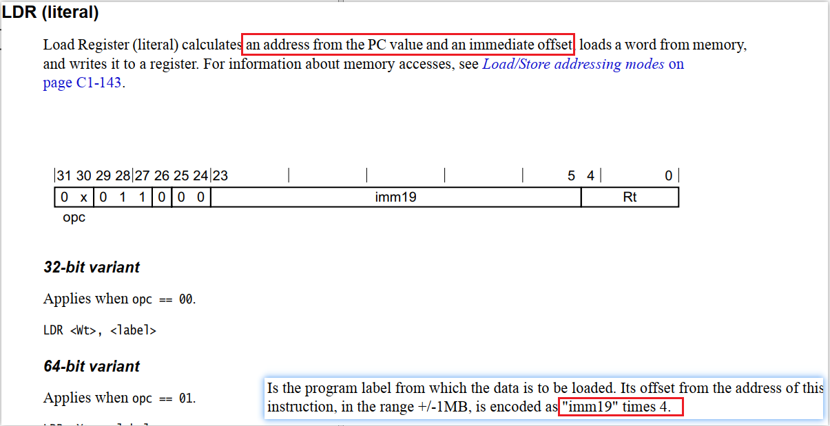
根据 opc 解析出 ldr 类型,lable is: ((0x580000c0 & 0xfff) >> 5) * 4 = 0x18
这样看下来,qemu内置的Bootloader实现加载DTB,并传递地址给内核入口,这段实现还是很巧妙的,需要对汇编指令然后bootload机制有系统的了解,代码还是比较清晰的。
核启动的执行第一条Guest指令是怎么个流程呢? 首先是设置PC(Program Counter)寄存器位置,可以通过CPUState的PC成员看调用点
@file: target/arm/cpu.h
struct CPUArchState {
    uint64_t xregs[32];  /* Regs for A64 mode.  */
    uint64_t pc;
    // ...
}

@file: include/hw/core/cpu.h
arm_cpu_set_pc(CPUState *cs, vaddr value)
arm_cpu_class_init
    cc->set_pc = arm_cpu_set_pc;
||
cpu_set_pc(CPUState *cpu, vaddr addr)
    cc->set_pc(cpu, addr);

@file: boot.c  // 使用qemu内置的boot,boot阶段就置位了PC
default_reset_secondary
    cpu_set_pc(cs, info->smp_loader_start);
||
do_cpu_reset(void *opaque)
    if (cs == first_cpu)
        cpu_set_pc(cs, info->loader_start);

<<---create machine finished---->>
do_cpu_reset(void * opaque) (\root\github\qemu\hw\arm\boot.c:757)
qemu_devices_reset(ShutdownCause reason) (\root\github\qemu\hw\core\reset.c:84)
qemu_system_reset(ShutdownCause reason) (\root\github\qemu\system\runstate.c:494)
qdev_machine_creation_done() (\root\github\qemu\hw\core\machine.c:156ed
qemu_machine_creation_done() (\root\github\qemu\system\vl.c:2677)
qmp_x_exit_preconfig(Error ** errp) (\root\github\qemu\system\vl.c:2706)
qemu_init(int argc, char ** argv) (\root\github\qemu\system\vl.c:3753)
main(int argc, char ** argv) (\root\github\qemu\system\main.c:47)

// 也是reset阶段,把所有roms的data写入对应系统的地址空间里面去的
#0  address_space_write_rom_internal (as=0x555557acc1c0, addr=1073741824, attrs=..., ptr=0x555557dac7d0, len=40, type=WRITE_DATA) at ../system/physmem.c:2936
#1  0x000055555615408f in address_space_write_rom (as=0x555557acc1c0, addr=1073741824, attrs=..., buf=0x555557dac7d0, len=40) at ../system/physmem.c:2956
#2  0x00005555559aa9bb in rom_reset (unused=0x0) at ../hw/core/loader.c:1282
#3  0x00005555561b6ded in qemu_devices_reset (reason=SHUTDOWN_CAUSE_NONE) at ../hw/core/reset.c:84
#4  0x0000555555d0e8ea in qemu_system_reset (reason=SHUTDOWN_CAUSE_NONE) at ../system/runstate.c:494
#5  0x00005555559b2107 in qdev_machine_creation_done () at ../hw/core/machine.c:1569
#6  0x0000555555d15947 in qemu_machine_creation_done () at ../system/vl.c:2677
#7  0x0000555555d15a47 in qmp_x_exit_preconfig (errp=0x5555575a9f60 <error_fatal>) at ../system/vl.c:2706
#8  0x0000555555d18276 in qemu_init (argc=8, argv=0x7fffffffdc48) at ../system/vl.c:3753
#9  0x00005555558ede00 in main (argc=8, argv=0x7fffffffdc48) at ../system/main.c:47
然后是TCG大循环开始执行翻译的第一条Guest OS指令
b mttcg_cpu_thread_fn 这个,首次断住,只有1个,secondary core还没启动。
看调用点事 mttcg_start_vcpu_thread, 断这个看调用栈

// 至少看这个时机,bootloader/kernel 还没load,tcg thread 已经OK
#0  mttcg_start_vcpu_thread (cpu=0x555557a4a030) at ../accel/tcg/tcg-accel-ops-mttcg.c:137
#1  0x0000555555d01633 in qemu_init_vcpu (cpu=0x555557a4a030) at ../system/cpus.c:649
#2  0x0000555555e89093 in arm_cpu_realizefn (dev=0x555557a4a030, errp=0x7fffffffd650) at ../target/arm/cpu.c:2387
#3  0x00005555561b5f29 in device_set_realized (obj=0x555557a4a030, value=true, errp=0x7fffffffd760) at ../hw/core/qdev.c:510
#4  0x00005555561c0071 in property_set_bool (obj=0x555557a4a030, v=0x555557a62390, name=0x5555566afdf1 "realized", opaque=0x5555576eb4a0, errp=0x7fffffffd760) at ../qom/object.c:2305
#5  0x00005555561bdf98 in object_property_set (obj=0x555557a4a030, name=0x5555566afdf1 "realized", v=0x555557a62390, errp=0x7fffffffd760) at ../qom/object.c:1435
#6  0x00005555561c2542 in object_property_set_qobject (obj=0x555557a4a030, name=0x5555566afdf1 "realized", value=0x555557a62370, errp=0x5555575a9f60 <error_fatal>) at ../qom/qom-qobject.c:28
#7  0x00005555561be312 in object_property_set_bool (obj=0x555557a4a030, name=0x5555566afdf1 "realized", value=true, errp=0x5555575a9f60 <error_fatal>) at ../qom/object.c:1504
#8  0x00005555561b56e9 in qdev_realize (dev=0x555557a4a030, bus=0x0, errp=0x5555575a9f60 <error_fatal>) at ../hw/core/qdev.c:292
#9  0x0000555555dfee79 in create_cpu (machine=0x555557918000) at ../hw/arm/mini-virt.c:88
#10 0x0000555555dff27c in mach_virt_init (machine=0x555557918000) at ../hw/arm/mini-virt.c:146
#11 0x00005555559b1f9e in machine_run_board_init (machine=0x555557918000, mem_path=0x0, errp=0x7fffffffd960) at ../hw/core/machine.c:1509
#12 0x0000555555d157cf in qemu_init_board () at ../system/vl.c:2613
#13 0x0000555555d15a3d in qmp_x_exit_preconfig (errp=0x5555575a9f60 <error_fatal>) at ../system/vl.c:2704
#14 0x0000555555d18276 in qemu_init (argc=6, argv=0x7fffffffdc68) at ../system/vl.c:3753
#15 0x00005555558ede00 in main (argc=6, argv=0x7fffffffdc68) at ../system/main.c:47
至于执行到第一条Guest指令,用qemu的boot的话,应该是那个boot的地址。CPU执行第一调Guest指令时,一定已经是翻译成Host了,这个涉及了访存(第一条boot指令时加载内存里的值到,那么会触发helper的访存操作,最终会访问到对应的地址
gdb --args qemu-system-aarch64 -nographic -readconfig mini-virt.cfg -plugin ~/github/qemu/build/contrib/plugins/libexeclog.so -d plugin

(gdb) b cpu_tb_exec
(gdb) r
Thread 3 "qemu-system-aar" hit Breakpoint 1, cpu_tb_exec (cpu=0x555557a4a730, itb=0x7fffa3e7e040, tb_exit=0x7fff63e79050) at ../accel/tcg/cpu-exec.c:448
448         CPUArchState *env = cpu_env(cpu);
(gdb) n
451         const void *tb_ptr = itb->tc.ptr;
(gdb)
453         if (qemu_loglevel_mask(CPU_LOG_TB_CPU | CPU_LOG_EXEC)) {
(gdb)
457         qemu_thread_jit_execute();
(gdb)
458         ret = tcg_qemu_tb_exec(env, tb_ptr); // 后面就是执行boot这个第一段TB的所涉及的指令,以及对应访存
(gdb)
0, 0x40000000, 0x580000c0, "ldr x0, #0x40000018", load, 0x40000018, RAM
0, 0x40000004, 0xaa1f03e1, "mov x1, xzr"
0, 0x40000008, 0xaa1f03e2, "mov x2, xzr"
0, 0x4000000c, 0xaa1f03e3, "mov x3, xzr"
0, 0x40000010, 0x58000084, "ldr x4, #0x40000020", load, 0x40000020, RAM
459         cpu->neg.can_do_io = true;
(gdb) bt
#0  cpu_tb_exec (cpu=0x555557a4a730, itb=0x7fffa3e7e040, tb_exit=0x7fff63e79050) at ../accel/tcg/cpu-exec.c:459
#1  0x0000555556184ee4 in cpu_loop_exec_tb (cpu=0x555557a4a730, tb=0x7fffa3e7e040, pc=1073741824, last_tb=0x7fff63e79060, tb_exit=0x7fff63e79050) at ../accel/tcg/cpu-exec.c:920
#2  0x000055555618522a in cpu_exec_loop (cpu=0x555557a4a730, sc=0x7fff63e790e0) at ../accel/tcg/cpu-exec.c:1041
#3  0x00005555561852f0 in cpu_exec_setjmp (cpu=0x555557a4a730, sc=0x7fff63e790e0) at ../accel/tcg/cpu-exec.c:1058
#4  0x0000555556185386 in cpu_exec (cpu=0x555557a4a730) at ../accel/tcg/cpu-exec.c:1084
#5  0x00005555561ab526 in tcg_cpus_exec (cpu=0x555557a4a730) at ../accel/tcg/tcg-accel-ops.c:76
#6  0x00005555561abc28 in mttcg_cpu_thread_fn (arg=0x555557a4a730) at ../accel/tcg/tcg-accel-ops-mttcg.c:95
备注
code_gen_buffer 中是TB翻译后的指令数据,不能够用gdb单步执行,好的办法是借助 -d in_asm,out_asm 或者 tcg plugin来分析。
运行u-boot
编译u-boot
git clone https://github.com/u-boot/u-boot
cd u-boot
git checkout v2024.04
make CROSS_COMPILE=aarch64-linux-gnu- qemu_arm64_defconfig O=build
cd build
make CROSS_COMPILE=aarch64-linux-gnu- -j
启动u-boot
u-boot是开源的bootloader,是 Bare Metal 裸机程序,用QEMU最简单的启动方法如下
qemu -M virt -nographic -cpu cortex-a57 -bios build/u-boot.bin

// 然后看 QEMU 的 info roms
(qemu) info roms
virt.flash0 size=0x102ba8 name="u-boot.bin"
/rom@etc/acpi/tables size=0x200000 name="etc/acpi/tables"
/rom@etc/table-loader size=0x010000 name="etc/table-loader"
/rom@etc/acpi/rsdp size=0x001000 name="etc/acpi/rsdp"
addr=0000000040000000 size=0x100000 mem=ram name="dtb"
(qemu) info mtree
0000000000000000-0000000003ffffff (prio 0, romd): virt.flash0  // 这个是 flash0
// 根据QEMU实现,这是一个 pflash,  Program Flash memory
使用u-boot引导OS
把编译出的linux镜像,通过u-boot命令加一个u-boot头,然后放入或者说生成 flash.img 里,后面在用QEMU -drive指定这个img,然后就用 u-boot 这个 bios 把内核引导起来了,上面的博文还有个自制的极简的arm64内核,试一下
apt install u-boot-tools
mkimage -A arm64 -C none -T kernel -a 0x40000000 -e 0x40000000 -n qemu-virt-hello -d build/kernel.bin uImage
# 把 uImage, virt.dtb 分别扩展到 32 M
fallocate -l 32M uImage
fallocate -l 32M virt.dtb
# 拼接
cat uImage virt.dtb > flash.img

# 运行
qemu-system-aarch64 -nographic \
    -machine virt -cpu cortex-a57 -smp 1 -m 2G \
    -bios u-boot.bin \
    -drive if=pflash,format=raw,index=1,file=flash.img

# u-boot 的命令
## 查看flash info, 由于前面在制作 flash.img 时简单的拼接了 uImage 和 virt.dtb
## 因此现在 uImage 在 0x0400_0000 位置,virt.dtb 在 0x0600_0000 位置
=> flinfo   // flash info

# 使用 fdt addr 0x06000000 和 fdt print / 可以检查设备树是否正确
# fdt: Flattened Device Tree(简称FDT)
=> fdt addr 0x06000000
=> fdt print /

# 使用 bootm 0x04000000 - 0x06000000 命令即可运行内核
# bootm: boot application image from memory (help bootm)
=> bootm 0x04000000 - 0x06000000
这篇博客中极简内核 helloworld:qemu-virt-hello 可以运行,参考的是交大教学OS的project,作者也是曾经的研究生助教。
待处理
但是 u-boot 引导时出现了 Bad Linux ARM64 Image magic! , 待定位原因。
QEMU加载bios流程
// 也是用到了 loader.c 里的一个实现
#0  rom_add_file (file=0x555557a3de50 "/root/github/u-boot/build/u-boot.bin", fw_dir=0x0, addr=0, bootindex=-1, has_option_rom=false, mr=0x555557a3cd50, as=0x0) at ../hw/core/loader.c:1076
#1  0x00005555559a50f6 in load_image_mr (filename=0x555557a3de50 "/root/github/u-boot/build/u-boot.bin", mr=0x555557a3cd50) at ../hw/core/loader.c:158
#2  0x0000555555df8105 in virt_firmware_init (vms=0x55555794d400, sysmem=0x5555576ed000, secure_sysmem=0x5555576ed000) at ../hw/arm/virt.c:1272
#3  0x0000555555dfaa8d in machvirt_init (machine=0x55555794d400) at ../hw/arm/virt.c:2091
#4  0x00005555559b1f9e in machine_run_board_init (machine=0x55555794d400, mem_path=0x0, errp=0x7fffffffd920) at ../hw/core/machine.c:1509
#5  0x0000555555d157cf in qemu_init_board () at ../system/vl.c:2613
#6  0x0000555555d15a3d in qmp_x_exit_preconfig (errp=0x5555575aaf60 <error_fatal>) at ../system/vl.c:2704
#7  0x0000555555d18276 in qemu_init (argc=8, argv=0x7fffffffdc28) at ../system/vl.c:3753
#8  0x00005555558ede00 in main (argc=8, argv=0x7fffffffdc28) at ../system/main.c:47

// 命令行, 根据bios的解析方法,那么 -bios 和 -M virt,firmware=u-boot.bin 作用一样, 实测也确实一样
qemu_init
    case QEMU_OPTION_bios:
        qdict_put_str(machine_opts_dict, "firmware", optarg);
        break;
而且,根据后面用到了 load_image_mr,这个是loader的实现,那么用 -device loader效果也一样,实测也是
即下面三种效果一样:
qemu -M virt -bios build/u-boot.bin -nographic -cpu cortex-a57
qemu -M virt,firmware=build/u-boot.bin -nographic -cpu cortex-a57
qemu -M virt -device loader,file=build/u-boot.bin -nographic -cpu cortex-a57
待处理
后面试一下引导标准linux.
MemoryRegion机制
研究一下TCG再翻译执行Guest汇编指令集的时候遇到访存指令(访问Memory)或者IO指令(访问IO),如何关联到QEMU的MemoryRegion的。这里主要针对ARM架构来研究,IO和访存物理地址空间合一。
针对前面的 v8.2.0分之的 mini-virt.c 的关键实现看,创建ram/mmio-dev时:
// @file: mini-virt.c
MemoryRegion *sysmem = get_system_memory()
create_ram(vms, sysmem)
    // Initialize RAM memory region. Accesses into the region will modify memory directly.
    memory_region_init_ram(&vms->ram, NULL, "ram", memmap[VIRT_MEM].size, &error_fatal);
            memory_region_init_ram_nomigrate(mr, owner, name, size, &err);
                    memory_region_init(mr, owner, name, size);

    // Add a subregion to a container, 第一个mr是container
    memory_region_add_subregion(sysmem, memmap[VIRT_MEM].base, &vms->ram);

create_uart
    memory_region_add_subregion(sysmem, base, sysbus_mmio_get_region(s, 0));

// Initialize an I/O memory region, 一般配合 sysbus_init_mmio 一起用
void memory_region_init_io(MemoryRegion *mr, Object *owner,
|                      const MemoryRegionOps *ops,  // read/write callback
|                      void *opaque, const char *name, uint64_t size);
memory_region_init_io
|   memory_region_init
sysbus_init_mmio(SysBusDevice *dev, MemoryRegion *memory);
    n = dev->num_mmio++;  // 把这个mr地址赋值给父类的,后面统一管理
    dev->mmio[n].memory = memory;

// 然后在 sysbus_mmio_map, 中可以统一映射 base-addr, 跟前面init的顺序意义对应起来
// 这个API也是加入到一个region下面去, 在create外设就是init完后经常用
// void sysbus_mmio_map(SysBusDevice *dev, int n, hwaddr addr);
sysbus_mmio_map(gicbusdev, 0, vms->memmap[VIRT_GIC_DIST].base);
    sysbus_mmio_map_common(dev, n, addr, false, 0);
        memory_region_add_subregion(get_system_memory(), addr, dev->mmio[n].memory);
访存指令读写system_memory时callstack:
(gdb) bt
#0  iotlb_to_section (cpu=0x800fc00, index=0, attrs=...) at ../system/physmem.c:2437
#1  0x00005555561984c6 in io_prepare (out_offset=0x7fff63e78958, cpu=0x555557a4b030, xlat=140735296503809, attrs=..., addr=18446603338413113320, retaddr=140734873285897) at ../accel/tcg/cputlb.c:1335
#2  0x000055555619baaf in do_ld_mmio_beN (cpu=0x555557a4b030, full=0x7fff5c0677c0, ret_be=0, addr=18446603338413113320, size=4, mmu_idx=2, type=MMU_DATA_LOAD, ra=140734873285897) at ../accel/tcg/cputlb.c:2030
#3  0x000055555619c610 in do_ld_4 (cpu=0x555557a4b030, p=0x7fff63e78a20, mmu_idx=2, type=MMU_DATA_LOAD, memop=MO_32, ra=140734873285897) at ../accel/tcg/cputlb.c:2336
#4  0x000055555619c978 in do_ld4_mmu (cpu=0x555557a4b030, addr=18446603338413113320, oi=34, ra=140734873285897, access_type=MMU_DATA_LOAD) at ../accel/tcg/cputlb.c:2418
#5  0x000055555619e337 in helper_ldul_mmu (env=0x555557a4d7f0, addr=18446603338413113320, oi=34, retaddr=140734873285897) at ../accel/tcg/ldst_common.c.inc:33
#6  0x00007fff642135f8 in code_gen_buffer ()
#7  0x0000555556184213 in cpu_tb_exec (cpu=0x555557a4b030, itb=0x7fffa4213380, tb_exit=0x7fff63e79050) at ../accel/tcg/cpu-exec.c:458

(gdb) p cpu->as->name
$9 = 0x555557a63490 "cpu-memory-0"
(gdb) p cpu->as->root
$10 = (MemoryRegion *) 0x555557748ee0
(gdb) p address_space_memory.name
$11 = 0x555557a38d80 "memory"
(gdb) p address_space_memory.root
$12 = (MemoryRegion *) 0x555557748ee0

// system/physmem.c --- 全局变量
MemoryRegion *system_memory;
AddressSpace address_space_memory;

TCG解释执行到访存指令,进入到下面的helper函数,查了下 chatGPT 为啥这么缩写,有道理:
helper_ldul_mmu 函数名中的 ldul 是 "Load Unsigned Long" 的缩写,表示该函数用于加载无符号长整型数据。
// 在 include/tcg/tcg-ldst.h 有一些的mmu相关的helper函数
// 在 tcg_out_ld_helper_args @@ tcg.c 里会有注册

helper_ldul_mmu
    do_ld4_mmu(env_cpu(env), addr, oi, retaddr, MMU_DATA_LOAD); // ld4 是 "Load 4-byte"
      do_ld_4(cpu, &l.page[0], l.mmu_idx, access_type, l.memop, ra);
          int_ld_mmio_beN  // beN, 意思是big endian吗? guest和host都是小端,奇怪
              io_prepare(&mr_offset, cpu, full->xlat_section, attrs, addr, ra);
                  section = iotlb_to_section(cpu, xlat, attrs); // find mr
                       CPUAddressSpace *cpuas = &cpu->cpu_ases[asidx];

#0  pl011_read (opaque=0xfffffffffffffe00, offset=36027463472, size=21845) at ../hw/char/pl011.c:147
#1  0x0000555556141b73 in memory_region_read_accessor (mr=0x555557d91a90, addr=4064, value=0x7fff636778e0, size=4, shift=0, mask=4294967295, attrs=...) at ../system/memory.c:445
#2  0x0000555556142181 in access_with_adjusted_size (addr=4064, value=0x7fff636778e0, size=4, access_size_min=4, access_size_max=4, access_fn=0x555556141b2c <memory_region_read_accessor>, mr=0x555557d91a90, attrs=...) at ../system/memory.c:573
#3  0x0000555556144e85 in memory_region_dispatch_read1 (mr=0x555557d91a90, addr=4064, pval=0x7fff636778e0, size=4, attrs=...) at ../system/memory.c:1426
#4  0x0000555556144fa3 in memory_region_dispatch_read (mr=0x555557d91a90, addr=4064, pval=0x7fff636778e0, op=MO_BEUL, attrs=...) at ../system/memory.c:1459
||
#5  0x000055555619b97f in int_ld_mmio_beN (cpu=0x555557af5980, full=0x7fff54078140, ret_be=0, addr=18446603338413039584, size=4, mmu_idx=2, type=MMU_DATA_LOAD, ra=140734941518592, mr=0x555557d91a90, mr_offset=4064) at ../accel/tcg/cputlb.c:1999
#6  0x000055555619baff in do_ld_mmio_beN (cpu=0x555557af5980, full=0x7fff54078140, ret_be=0, addr=18446603338413039584, size=4, mmu_idx=2, type=MMU_DATA_LOAD, ra=140734941518592) at ../accel/tcg/cputlb.c:2034
#7  0x000055555619c610 in do_ld_4 (cpu=0x555557af5980, p=0x7fff63677a20, mmu_idx=2, type=MMU_DATA_LOAD, memop=226, ra=140734941518592) at ../accel/tcg/cputlb.c:2336
#8  0x000055555619c978 in do_ld4_mmu (cpu=0x555557af5980, addr=18446603338413039584, oi=3618, ra=140734941518592, access_type=MMU_DATA_LOAD) at ../accel/tcg/cputlb.c:2418
#9  0x000055555619e337 in helper_ldul_mmu (env=0x555557af8140, addr=18446603338413039584, oi=3618, retaddr=140734941518592) at ../accel/tcg/ldst_common.c.inc:33
#10 0x00007fff68325b50 in code_gen_buffer ()
每个tcg thread,翻译执行guest汇编指令时,都会通过helper函数去访问自己 CPU ENV 的地址空间。CPU ENV怎么和AddressSpace关联起来的呢,看下 mini-virt 创建 CPU obj的流程
@file: mini-virt.c
create_cpu
    Object *cpuobj = object_new(possible_cpus->cpus[i].type);
    |   object_initialize_with_type
    |       // qom机制
    |       cpu_common_initfn // .instance_init
    |           cpu_exec_initfn(cpu);
    |               // DEFINE_PROP_LINK("memory", CPUState, memory, TYPE_MEMORY_REGION, MemoryRegion *)
    |               cpu->memory = get_system_memory(); // 默认值,也定义了 property 赋值,很方便
    |
    CPUState *cs = CPU(cpuobj);
    qdev_realize(DEVICE(cpuobj), NULL, &error_fatal);
        // qom机制
        arm_cpu_realizefn
        |   cpu_address_space_init(cs, ARMASIdx_NS, "cpu-memory", mr: cs->memory); // cs-memory, type memroy_region
        |       AddressSpace *as = g_new0(AddressSpace, 1);
        |       as_name = g_strdup_printf("%s-%d", prefix, cpu->cpu_index);
        |       address_space_init(as, mr, as_name);  // <-- 初始化 AddressSpace, 都是用 system_memory
        qemu_init_vcpu(cs);
            if (!cpu->as): // 如果没有address spaces,用默认
                cpu_address_space_init(cpu, 0, "cpu-memory", cpu->memory);

@fun: address_space_init
address_space_init(AddressSpace *as, MemoryRegion *root, const char *name)
    as->root = root;
    address_space_update_topology(as);
    |   MemoryRegion *physmr = memory_region_get_flatview_root(as->root);
    |   flatviews_init(); // init only once
    |       flat_views = g_hash_table_new_full // hash-table
    |   if (!g_hash_table_lookup(flat_views, physmr))
    |       generate_memory_topology(physmr); // 渲染成不交叉的绝对范围
    address_space_update_ioeventfds(as);